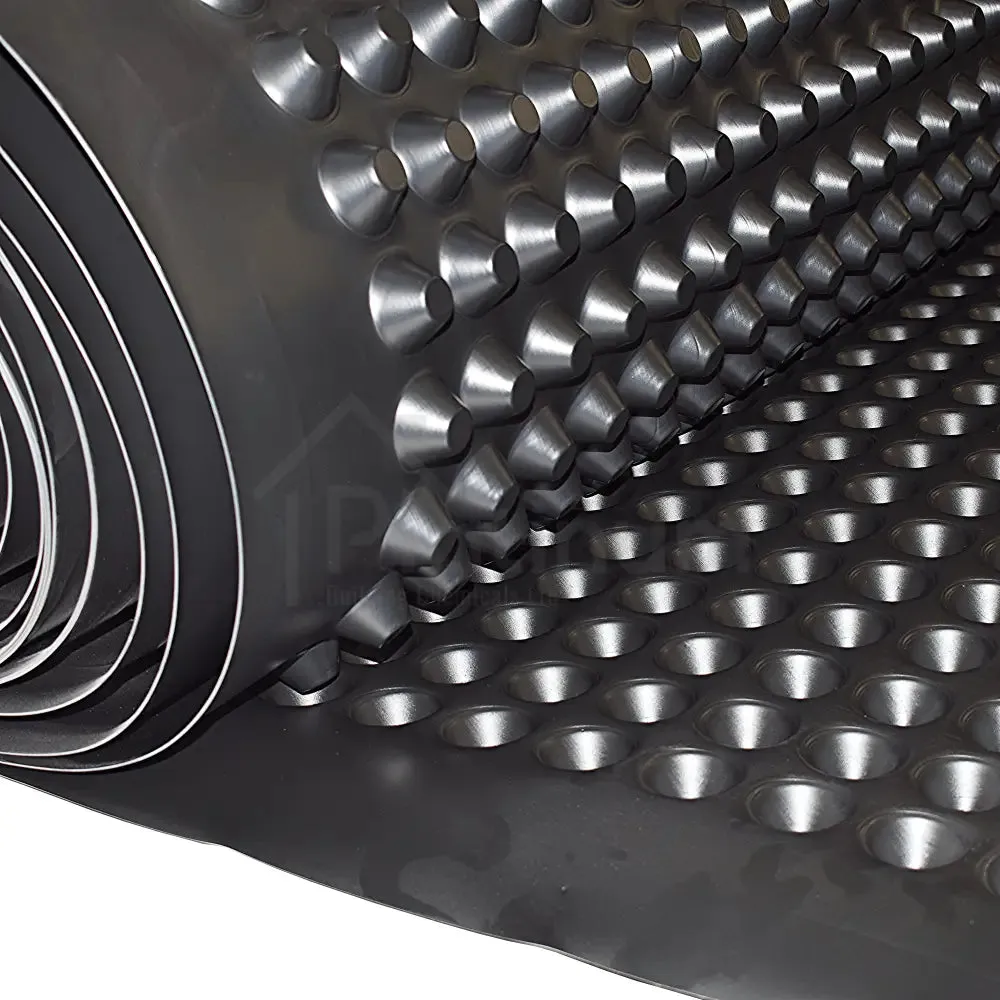

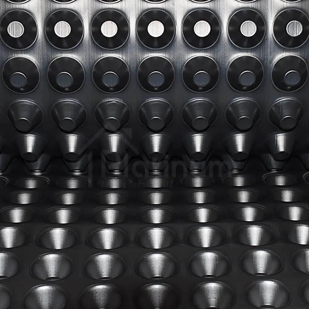
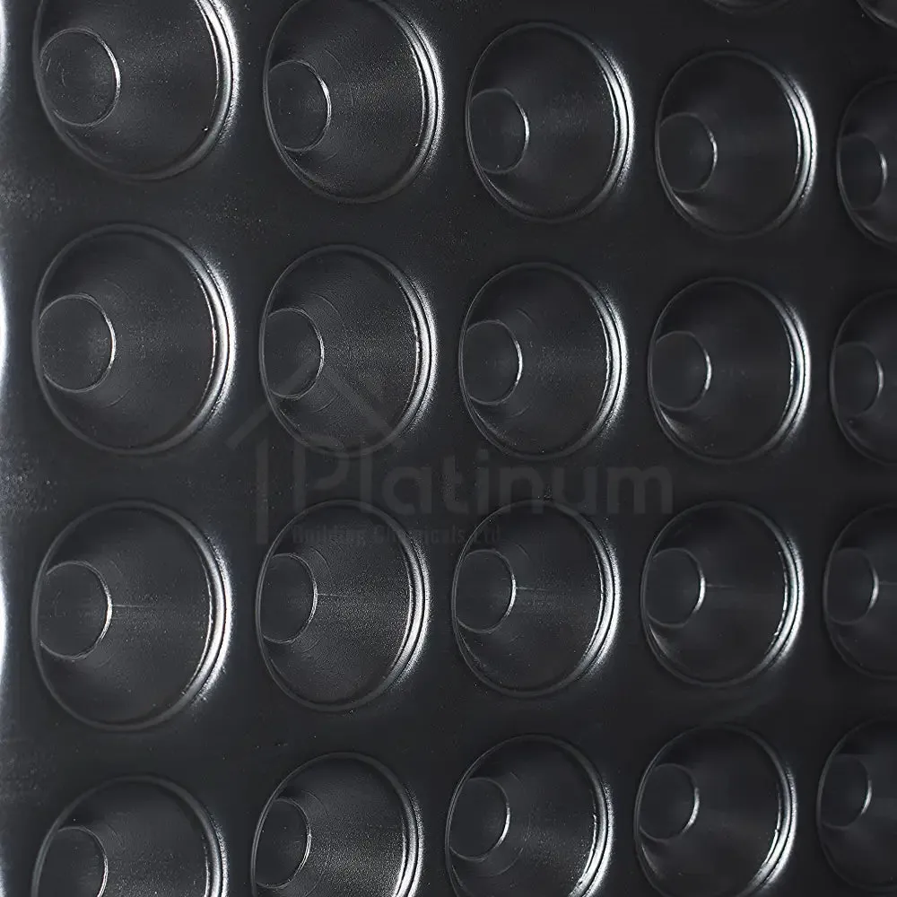
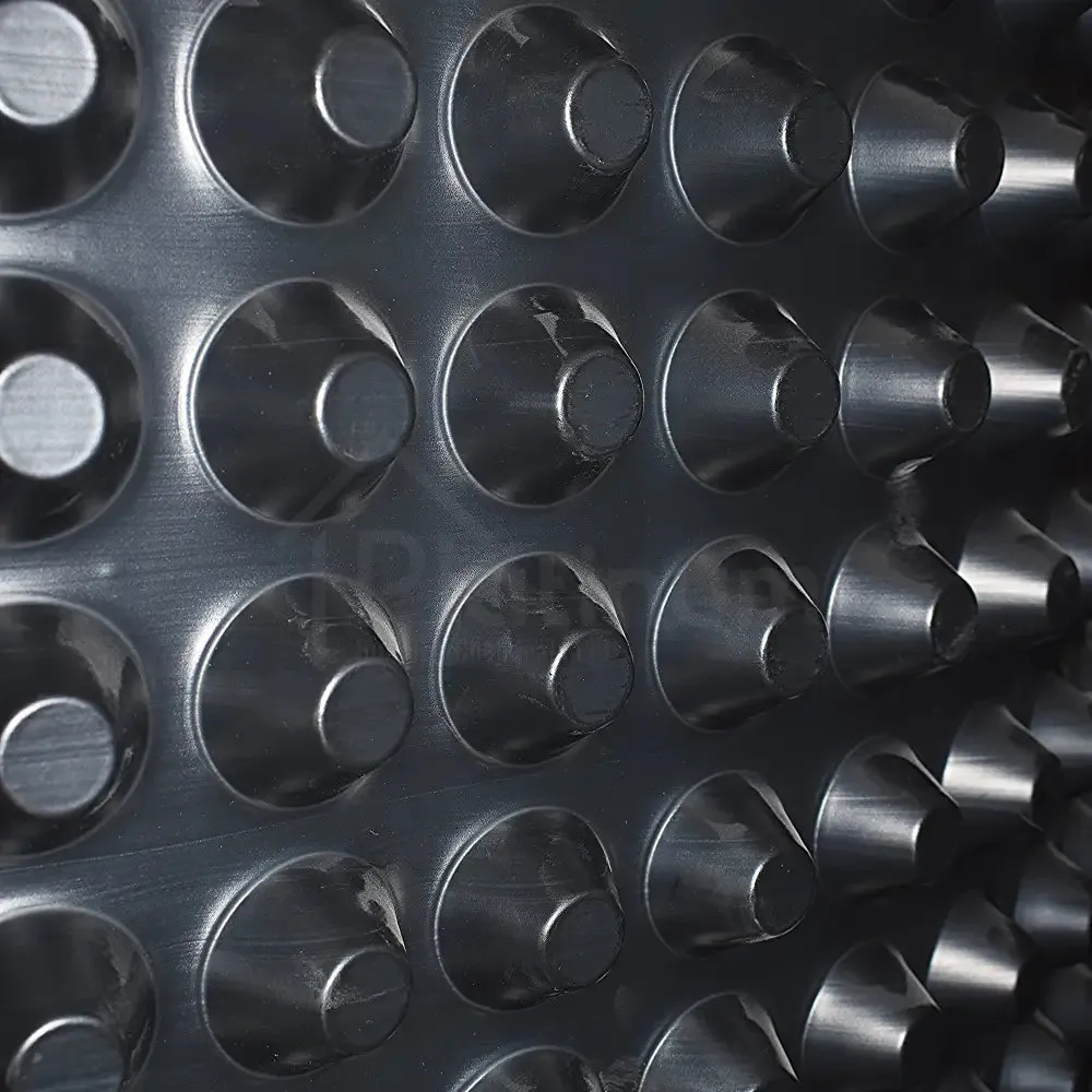

Newton 520 is a High Quality, BBA Approved, 20mm Stud Basement Tanking Floor Membrane.
One of the main constituent parts of 'Newton System 500', Newton 520 is used for the waterproofing of floors within earth retained structures, that includes drainage channels sited below the membrane for increased drainage capacity.
Newton 520 is supported by BBA Certification Certificate Number 94/3010.
Available in (W) 2.07M x (L) 10M (20M²) and (W) 2.07M x (L) 20M (40M²) Rolls.
Description
Newton 520 Cavity Drain Floor Membrane
Newton 520 is a Cavity Drain Waterproofing Membrane made from recycled High Density Polyethylene (HDPE).
It is one of the main constituent parts of Newton System 500, Newton's BBA Certified, ‘Type C’ Cavity Drain System, used for waterproofing of floors within earth retained structures, that includes drainage channels sited below the membrane for increased drainage capacity.
With its 20mm deep stud profile, Newton 520 is used within Newton System 500 as a high drainage capacity floor membrane and is generally specified where it is anticipated that there may be a risk of severe water penetration.
Newton 520 is guaranteed against deterioration for 30 years, with a life expectancy of at least the design life of the building (DIN 9001:2000).
Newton 520 is inert and, therefore, non-polluting to drinking water, highly resistant to water, alkalies, saline solutions and organic acids, and not affected by minerals and hydro-carbons. It is also impervious to root penetration, is rot-proof, and resistant to bacteria, fungi and other small organisms.
Benefits & Features:
-
Speed of installation
-
Made from 100% recycled HDPE
-
Provides vapour control and, when used with humidity control systems and is capable of delivering an environment to all levels within a Grade 3 environment to BS 8102:2009
-
Resistant to rot, chemically aggressive groundwater, acids and alkalines, efflorescing salts and hydrocarbon contamination
Technical Data:
| Membrane Material | HDPE |
| Membrane Thickness | 1.0mm |
| Stud Depth | 19.0mm |
| Density | 1000g/m² |
| Vicat Softening Temperature | 126°C |
| Service Temperature | -40°C to 80°C |
| Compressive Strength (EN 25619-2) | 240 kpa |
| Thermal Conductivity (EN12667) | 0.461 W/mK |
| Water Vapour Resistance - Sd Value (BS EN 1931) | >604m |
| Water Vapour Resistance - μ Value | >1208000μ |
| Water Vapour Diffusion Resistance | >3020 MNs/g |
| Resistance to Fire (BS EN 13501-1) | EuroClass |
| Chemical Resistance - Excellent (EN 14030) | 100% |
| Oxidation Resistance - Excellent (EN ISO 13438) | 100% |
| Radon Gas Resistance - Membrane* (K124/02/95) | N/A |
| Radon Gas Resistance - Joints* (K124/02/95) | N/A |
| Resistance to Liquid Hydrocarbons* (EN 16140:2011) | N/A |
| Carbon Dioxide Permeability* | N/A |
| Methane Permeability* | N/A |
| Carbon Dioxide Transmission Rate (ISO 15105-1) | N/A |
| Methane Transmission Rate (ISO 15105-1) | N/A |
Installation
Preparation:
Newton 520 should only be used on floors. Before the system is installed, the area must be assessed to determine what preparation is required:
All timber and other organic material must be removed to prevent risk of fungal or bacterial growth behind the System. If evidence of rot exists, this must be dealt with by a specialist contractor prior to installation of the system (See our Products).
Brush the floor clean and remove any sharp protrusions. Fill all non-structural cracks above 1mm wide, all structural cracks should be repaired or treated.
New concrete should be treated with which prevents free lime from the curing concrete being drawn out by ingressing water.
Drainage Requirements
When used in a full or part earth-retaining situation, the membrane system must be drained. To comply with BS 8102:2009, you must assume that the structure will be subjected to water ingress at some time.
Methods Of Drainage:
The drainage must effectively remove all water from below the membrane and take the water to a point of discharge such as a Sump Chamber or a form of safe natural drainage. Standing water can block the membrane with silt or lime scale so it is important for water to flow uninterrupted to the drainage point.
is placed at the wall / floor junction and collects water from behind the wall membrane and receives water at the wall / floor junction. is a designed method of removing water as it can interface with sump chambers, gullies, waste pipes etc.
It can also be maintainable by inserting into the system.
Installation:
It is very rare for water to pass through a solid concrete slab or concrete raft, but where the slab or raft is of questionable quality it is possible for water to pass through cracks in a poorly constructed floor. If the quality of the slab is questionable, Newton 520 should be used as the floor membrane.
Starting at one side of the room, unroll the membrane with the studs down and cut to fit the room as one would a carpet. The next membrane width is rolled out so that the flanged edge overlaps onto the edge of the previous roll of membrane. Clean both edges.
is then applied to the high flat area between the first two studs at the edge of the previous roll of membrane with the backing paper still intact.
Check the two widths for alignment, with the flange covering the backing paper.
Starting from the end of the joint, remove the backing paper and press down on the joint sealing the two sections together. This process is repeated until all areas are covered. Seal the Newton 520 Membrane to the up-stand of the perimeter drainage channel with .
Where the floor membrane is required to be jointed to horizontal DPC’s through internal and external walls, these joints should be sealed with . Ensure both surfaces are clean and dry before attempting to make these joints.
If there are any services up through the floor, the membrane can be cut and trimmed around them, and the gap filled and sealed using a high quality .
If necessary, a patch of membrane or is laid over and sealed to the service with , and around its perimeter with .
It should be noted that protrusions through the floor slab/raft should be avoided wherever possible as they create weaknesses that allow unnecessary water ingress.
The specified floor finish can now be laid directly over the floor membrane, which must not be punctured by any fixings through the floor. When a timber floor finish is preferred you must allow an expansion gap around the wall edge.
Speak to the supplier of the floor finish to confirm the correct size of this expansion gap.


")


